The development history of LED strips light
In 1923, 0.W. Lessew first observed silicon carbide P-N junctions with unidirectional conductivity and luminescence. This discovery was revolutionary for the time, but it was until around 1955 that breakthroughs were made in studying semiconductor theory and luminescence phenomena. By 1960, scientists used phosphorus to invent the first visible red light LED on the GaAs substrate.
In 1969, scientists developed a LED using the principle of semiconductor PN junction diode. The material used in the LED developed at the time was the GaASPs luminous color of red. This was also the time period made famous by Route 66, New York, Paris, Rome, and other major cities embraced LEDs in their signage and instrumentation.
In 1985, scientists introduced aluminum into GaAs materials and successfully developed the first generation of high-brightness LED. By the early 1990s, LED light sources proliferated after Nippon Chemical Nakamura successfully produced high-brightness blue and green light-emitting diodes on the GaN base material. The white light LED light source was successfully developed in 1998.
The China LED industry began to develop in the 1960s. After seeing how widespread the use of the technology had become, they formally creating an industry in the 1980s and had scaled up productivity by the 1990s.
In recent years, China’s high-brightness LED industry has been developing rapidly, closely following the world’s LED industry development. The upstream of the LED industry chain is the LED epitaxial wafer and chip industry. Since 2009, the government has heavily subsidized LED chip companies, and capital has poured in, resulting in excess upstream capacity and continued declining LED chip prices.
After more than ten years of fierce competition, the concentration of the LED chip industry has gradually increased. As a result, major manufacturers such as Sanan Optoelectronics Co., Ltd, China Star Optoelectronics Technology Co., Ltd, and Jiangsu Azure Corporation Cuoda Group Co., LTD accounted for more than 70% of the domestic market, and the industry integration was basically completed.
The middle reaches of the LED industry chain is the LED packaging industry. Like the upstream, the LED packaging industry has also experienced price wars due to capacity expansion. Some small and medium-sized manufacturers have been eliminated, causing the industry concentration to gradually increased and integration trends to be completed. The leading manufacturers in the domestic packaging industry include Forest light, Ever light, and National Star.
The downstream of the LED industry chain is the LED application industry. The LED application industry has an ample market space and low thresholds, coupled with the price wars in the upper and middle reaches in recent years. This has resulted in many downstream companies, and the market is currently in a stage of high competition. The domestic LED application industry enterprises include OPPLE Lighting, NVC Lighting, Yankon Lighting, FOSHAN ELECTRICAL AND LIGHTING CO., LTD, and PAK Corporation Co. Ltd.
The classification of LED strips
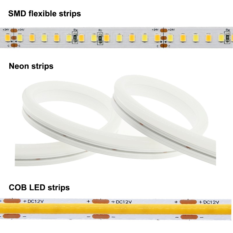
LED flexible light strips are divided into SMD flexible strips, neon strips, and COB LED strips. The differences are as follows:
-
The structure of various flexible light strips is different
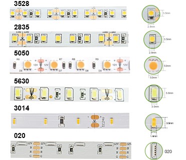
(a) The SMD flexible led strip uses FPC to assemble circuit boards, and SMD LED for assembly. The product is only 1mm thick, which does not take up space. The general specifications are 30, 48, 60, 90, 120, 240 lights per meter.
Different users have different specifications, and the strips can be cut at will to create extensions without affecting the light emission. The FPC material is soft, can be bent, folded, wound, moved, and stretched in three-dimensional space without breaking. It is suitable for use in odd places with small spaces. Due to its free form flexibility, it can be modified for various patterns in advertising decoration.
It is worth reminding that FPC itself is divided into many kinds of materials. The most common used in the market is double-sided FPC made of RA, Rolled-Annealed copper. Of course, some companies blindly pursue material cost reduction and adopt FPC made of ED, Electrodeposited copper (ED FPC). It is easy to peel off during the welding process, which directly leads to the phenomenon of false soldering and dead lamps. In addition, the electrodeposited copper PCB cannot compete with the RA copper PCB in terms of electrical conductivity and flexibility.
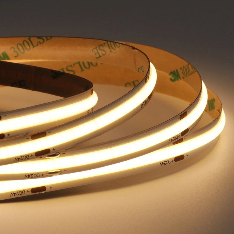
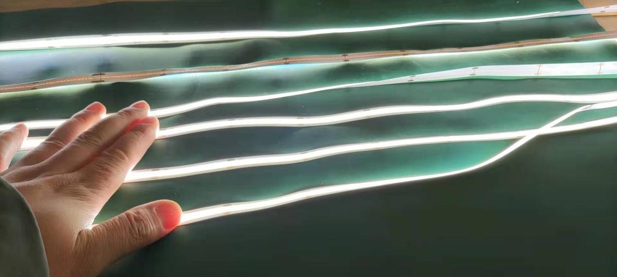
(b) COB is the abbreviation of Chip on Board, which is a method of directly building the Led Chips to the PCB Board. Chips are mostly flip-chips, which are linearly packaged on the PCB, and then a layer of packaging glue mixed with phosphor is directly dropped on the surface of the chip.
This is a new type of flexible LED strip launched in the LED strip market over the past two years. COB LED strips have apparent advantages such as high brightness, substantial uniformity, and high lamp bead density, which quickly subverted the public’s perception of LED light strips in the colorful linear lighting market.
In addition, since the COB chip is directly packaged on the PCB board, the chip’s heat can be quickly transferred to the PCB board. Therefore, the heat dissipation speed of the chip of the COB LED strip is faster than that of the bead-type lamp, and the light decay of the COB LED strip is more minor while the life span is longer.
(c) The neon light strip in the LED is sleeved in silicone, showing colorful light. Neon light strips are divided into one-piece and split-type. The one-piece neon light strip is formed by putting the light strip into the machine then combining them together. The split-type light strip and led strip are put into the sleeve after being made into a finished sleeve. The neon light strip has the advantages of good astigmatism, uniform luminescence, shockproofing, and waterproofing. It can fit all kinds of smooth surface materials.
-
The difference in working principle
(a) The SMD flexible led strip is a luminous lamp bead affixed to the PCB board. After the current is applied, the tiny lamp beads light up.
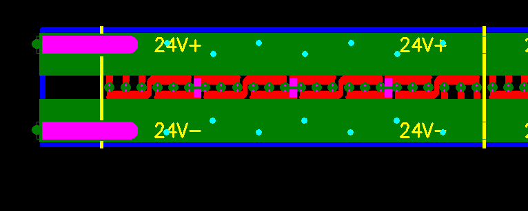
(b) COB LED strips use flip-chips to encapsulate the chip on a flexible board. The chip is firmly linearly bonded to the PCB. Then a layer of encapsulating glue mixed with phosphorus is directly applied. The appearance is similar to a piece of ramen pasted on a PCB board.
The light emitted by the chip undergoes refraction, reflection, and interaction in the packaging colloid. This colloid uniformly emits light of different colors and color temperatures. Therefore, the light emitted by the COB lamp belt should be much more uniform, linear, and dot-free.
(c) The finished neon led strip with different colors are covered with silicone sleeves. After the power is on, the neon strips light up. The different colored light is refracted, reflected, and interacted by the external silicone sleeves to emit uniform light.
SMD flexible led strip production process:
-
Preparation work before SMD flexible led strip production:
(a) Read the order requirements carefully and confirm that the led strip voltage requirements are 5V/12V/24V.
(b) Test the VF value and direction of the LED.
(c) Prepare resistors and capacitors.
(d) Weld the LED and resistor, and then use a multimeter to test whether the current is standard.
2 Printing solder paste
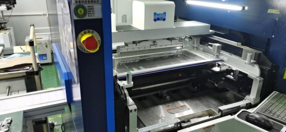
(a) Stir the solder paste after returning to temperature (LF-180A can be used directly by stirring).
(b) Put a small amount on the stencil of the printing machine (LTCL-SP600). The amount should be 3/2 of the solder paste to the squeegee when the squeegee advances.
(c) After the first trial printing, pay attention to whether the solder paste at the LED pad position on the FPC is full, whether there is less or more tin, and whether there is a short circuit. This check is critical. Without proper attention, this could result in poor quality later on.
-
The patch (SM421S)
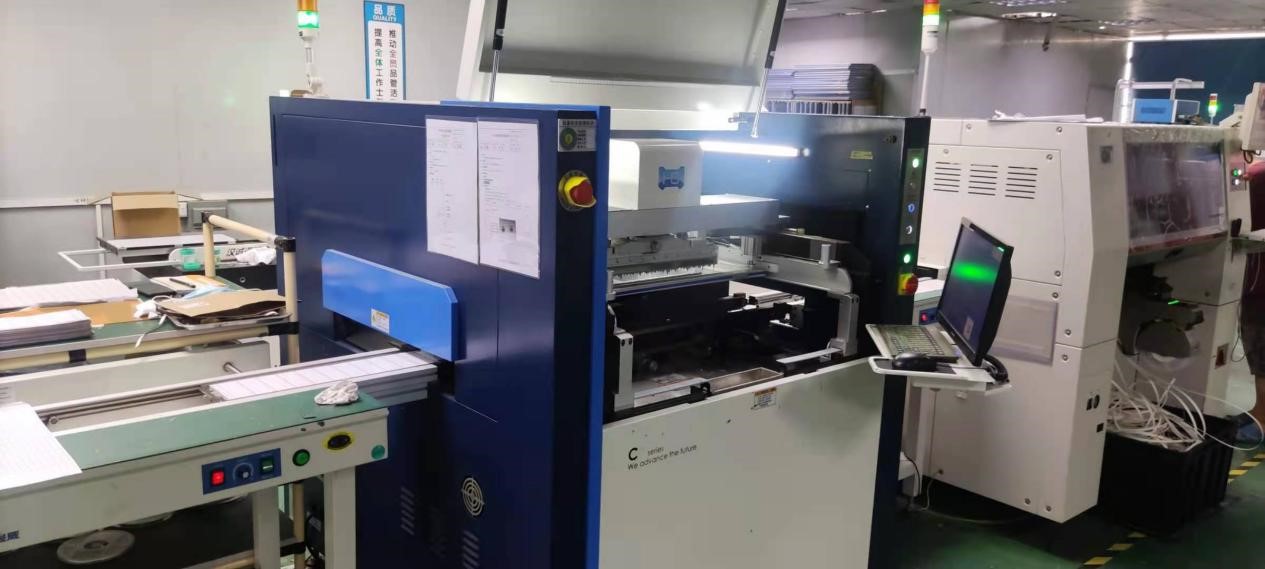
(a) Put the printed FPC on the fixture and automatically send the board to the placement position. The placement machine is programmed in advance. As long as there is no problem with the placement of the first board, the subsequent production will be stable. What needs attention here is the polarity of the LED and the resistance value of the chip resistor.
https://www.youtube.com/watch?v=StOaMT8Mi4s
-
Just don’t confuse it.
(a) Another thing to pay attention to is not to shift the mounting position or the intermediate inspection links.
(b) Need to check the polarity of the LED on the LED strip (whether it is reversed), whether the mounting is offset, whether there is a short circuit, whether the resistance value is correct, etc.
-
Reflow soldering (M6/S6)
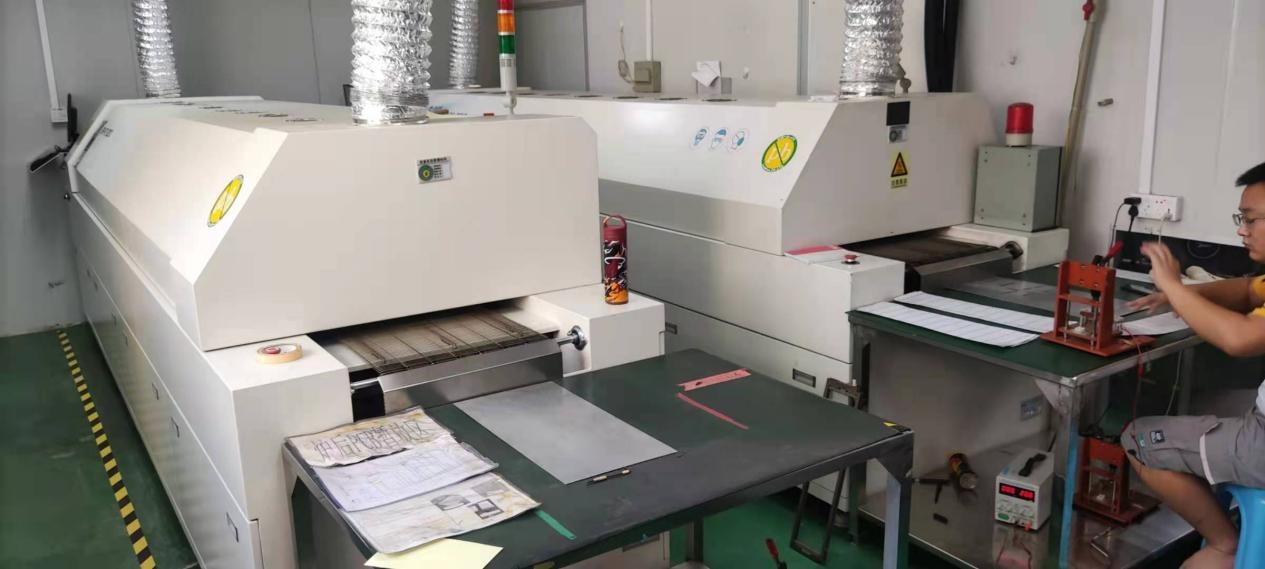
(a) First, set the temperature curve parameters of the reflow soldering machine.
(b) Then, put the PCB board with the components attached into the reflow soldering machine.
(c) After a few minutes, the PCB board will come out. Carefully check the quality of the PCB, whether the board is discolored, whether the tin is completely melted, and whether the solder joints are smooth.
(d) Finally, according to the test results, adjust the parameters of the previous process, such as brushing solder paste, patching, over-reflow soldering, and other process parameters.
It should be noted here that the reflow temperature must be well controlled. If it is too low, the solder paste will not melt, and cold soldering will occur; the FPC is prone to blistering if it is too high. Also, the preheating temperature should be appropriate. If the temperature is too low, the flux will not evaporate completely, and there will be residues after reflow, which will affect the appearance.
-
Detect PCB semi-finished boards
(a) Check the product’s appearance to see if there is any poor soldering, tin bead, short circuit, etc.
(b) Ensure the electrical performance is intact and whether the parameters are correct.
(c) Firstly, cool the half product out of the furnace. Then, visually check for any phenomenon such as false soldering, misalignment, etc. Then use the power supply to light up the product.
(d) Pay attention to observe the LED chips and whether they can all light up. If the chips are not lit, check the most common problems, including:
A: LED has false soldering.
B: The LED is misplaced, and the lamp pin is not on the corresponding solder joint.
C: Resistance false soldering.
D: LED is necrotic.
If the above problems are found after inspection, targeted repairs and corrections should be made.
The difference between the advantages and disadvantages of PCB boards:
(a) Identify the quality of the circuit board from the appearance: standard rules for size and thickness. The thickness of the circuit board is different from that of the standard circuit board. Customers can measure and check the thickness and specifications of their own products.
(b). Check the light and color. The external circuit board is covered with ink, and the circuit board can play the role of insulation. If the board’s color is not bright and has less ink, the insulation board itself is not good.
(c). The appearance of the weld seam. Circuit boards have many parts. If the welding is not suitable, the parts will easily fall off the circuit board, seriously affecting the welding quality. It is essential to have a good appearance, careful identification, and a robust interface.
(d). The most commonly used and economical conductor material in flexible boards is copper foil. Copper foil is mainly divided into ED and RA. Electrodeposited copper foil is formed by electroplating. RA is much better.

High-quality PCB circuit boards need to meet the following requirements:
(a) The line is required to be easy to use after the components are installed. That is, the electrical connection must meet the requirement.
(b) The line width, thickness, and distance must meet the requirements to prevent the line from heating, breaking, and short-circuiting.
(c) The copper skin will not easily fall off under high temperatures.
(d) The copper surface is not easy to oxidize, which affects the installation speed. It will be broken soon after being oxidized.
(e) There is no additional electromagnetic radiation.
(f) The shape is not warped to avoid deformation of the housing and dislocation of the screw holes after installation. They are all mechanized installations, the hole position of the circuit board, the deformation error of the circuit, and the design should be within the allowable range.
(g) High temperature, humidity, and particular environment resistance should also be considered.
(h) The mechanical properties of the surface must meet the installation requirements.
-
Connection
(a) Connect the terminal wire at the joint. First, strip the two ends of the cable, add tin and strip one end to a length of 3 mm.
(b) Cable color requirements: black wire is connected to GND, the red wire is connected to 5V, and the yellow is connected to “Din.”
(c) The welding wire is welded according to the direction of the arrow signal on the FPC board.
(d) After connecting it, test it with a stabilized power supply. Check carefully where it is not bright, and fix it. The repaired lamp must be baked in the oven for more than 12 hours before being used.
(e) Welding requirements: Soldering iron temperature: 300 degrees
Time: no more than 3 seconds seven.
-
Blow white heat shrink tubing
After welding, put on a white heat-shrinkable tube (15mm) at the joint. The heat-shrinkable tube can be placed next to the lamp (not cover the lamp beads). Then use a hot air cylinder to blow the heat-shrinkable tube tightly.
-
Glue
(a) The aging led strip is neatly placed on the glue tooling.
(b) Adjust the glue according to the ratio of the glue factory, stir it evenly, vacuum, and then use the machine to evenly drop the glue on the PCB.
(c)The glue should be immersed in the LED light to ensure that the glue is not uneven. If there are bubbles, use tweezers to pierce them. If the glue leaks, make up the glue. It will take more than 5 hours for the glue to dry.
Note: The soft light strips with good glue are placed neatly on the workbench. Make sure the adhesive paper is neatly affixed to the back of the strip light, leaving 1CM soil 2MM at the end not to be pasted. Then flow the adhesive tape to the next station.
Distinguish between the pros and cons of glue:
Among the materials used for waterproof led strips, the epoxy resin AB glue 560 series is currently more commonly used in the market. However, the light strips encapsulated by this glue generally exhibit defects such as many bubbles, are easier to break, are not resistant to high temperature and severe cold weather, are easy to turn yellow, and are easy to tear after long-term use. One of the most common customer complaints is from using this type of glue.
We currently use polyurethane glue. Polyurethane is a good glue. It is more expensive, but it has good transparency and will not break after 500 times of repeated folding. It is tear-resistant, outdoor UV-resistant, and permanent non-yellow.
The product made of excellent surface gloss has excellent low-temperature resistance, water resistance, ozone resistance, acid and alkali resistance, alcohol resistance, arc resistance, ultraviolet light resistance, cold and heat cycle impact resistance, and other properties to fully meet the high-performance requirements for indoor and outdoor use.
https://www.youtube.com/watch?v=-8du4qBmK7U
-
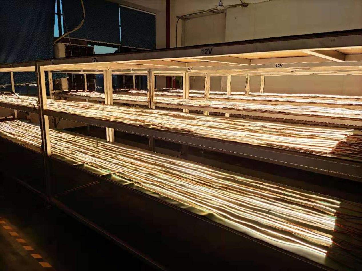
Finished product testing
(a) The light strips with adhesive tape are placed neatly on the workbench for carry out testing.
(b) First, carry out the appearance test. Look at the glue surface. Then, re-test rack to test product functions.
(c) Note that good products and defective products must be opened separately. Defective products are placed in the defective area and returned to the maintenance personnel for repair. Good products flow into the next station for packaging.
-
Packaging
(a) Count the number of LED strips first. You want a pack of 50 strips before tying them together with 3M crepe tape.
(b) Then wrap 50 products with white pearl cotton and cover them with sealing tape.
(c) The white pearl cotton package is affixed with a hospitality label.
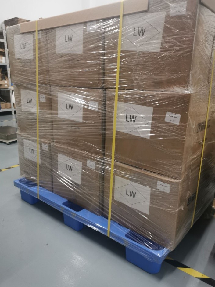
(d) Put the wrapped light strips into the standard outer box, 5 packs per layer, 4 layers, and each layer of light strips separated by cardboard.
(e) The direction should be consistent and tidy when packing.
(f) Paste the corresponding label and box number on the outer carton.
COB led strip light production process
- First, apply the solder paste to the PCB pad through the automatic solder paste brushing machine. The uniformity and thickness of the solder paste determine the quality and flatness of the soldered chip and the quality of the soldered chip.
- Load the solder paste-coated PCB board on the carrier. Input and set the die bonding program of the chip through computer programming. Then debug the direction and height of the die bonding, and confirm the electrode direction of the chip.
- Do a small-batch bond test first by inspecting the appearance quality of the PCB has a good bond direction, whether there is solder paste connected, and whether the location of the bond is correct. The inspected product flows into the following process.
- Put the solid-chip PCB board and wafer into the reflow soldering. Set the temperature and speed of the reflow soldering. Next, solder the LED chip firmly in the reflow soldering, and conduct an electrical test after it is out of the oven to test whether the LED chip emits normally.
- After testing the LED chips on the PCB board, perform the powder mixing process of silica gel and phosphor powder. According to the customer’s photoelectric parameters such as color temperature and brightness, configure different proportions, and degas the glue with the vacuum.
- Fix the PCB board on the dispenser carrier for the dispensing process. The dispensing process is the most critical process for the success of the strip light. After dispensing, put the PCB board in the oven, and the glue from different manufacturers is baked. If the baking conditions are inconsistent, refer to the manufacturer’s requirements for verification before setting the appropriate baking temperature.
- Test the color temperature of the light strip after the glue is dispensed and see if the test data meets the customer’s requirements.
- After welding a 0.5-meter PCB board, connect it to requirements ranging from 5-10 meters. Then, cut the entire circuit board into strips
- Continuously energize for 6-8 hours for proper aging.
- After the end of aging, perform a function and endurance test.
- If there is no problem during the function test, apply glue and wrap the light strip with a reel.
- Conduct a whole plate test to determine whether there are any bad conditions through the squeeze and twist test
- Pack the entire plate of COB LED strips in bags and prepare for shipment.
Neon strip production process
- Pour the neon light silicone tube raw materials into the production equipment, and produce silicone tubes with different shapes and different thicknesses according to the needs of customers
- Use solder to connect the PCB. It is worth noting that when connecting the board, the solder should be as flush as possible with the LED SMD. If there is too little solder, the PCB board will break easily.
- Use a long flat rubber strip to insert the cotton thread into the silicone sleeve, and then use an air gun to blow into the sleeve until the cotton thread is blown out to the other end.
Note: If the length of the blowing line is 10 meters or more, the cotton thread will be blocked in the casing due to insufficient gas. You can plug the end of the silicone casing with your hand to let the gas expand in the casing and then let go. You can try this back and forth process several times until the cotton thread can smoothly come out from the other end.
- Use a section of cotton thread to tie the neon light bare board. A length of fewer than 5 meters can be directly pulled into the silicone sleeve with cotton thread. If it is more than 5 meters, a thin wire needs to be welded on the bare board first and then pulled through the silicone sleeve.
- Use scissors to cut off the excess silicone sleeve at a position of 1 cm on the circuit board.
- Use glue to put a layer of low glue between the bare board and the silicone sleeve. Fix the two and then put glue around the silicone sleeve to then encapsulate.
- Finally, the neon light bar needs to be energized continuously for 24 hours for proper aging.
- After the aging is over, reel and arrange the neon led strip, and then test whether the neon led strip is defective or not by squeezing and twisting.
- Put it into the packaging bag, ready to ship.
LED has the characteristics of environmental protection, energy saving, bright colors and long service life. Widely used in: various buildings, indoor and outdoor local or outline lighting, especially suitable for indoor and outdoor entertainment venues, building outlines and billboard production, etc. After decades of development, LED lights are cheaper and more stable in quality, and there will be better development in the future to benefit mankind.
